I've been playing around with KVM on CentOS 7 in preparation for the RHCE exam. I was experiencing an issue where the guest virtual machine would freeze just before attempting an install (again, CentOS 7 as the guest).
The testing machine is quite old (has an Intel Core 2 6400 CPU) but it hasn't shown any other symptoms of hardware issues.
The logs didn't appear to show anything of interest other than some debugging information which is apparently normal:
[20389.379023] kvm [19537]: vcpu0 unhandled rdmsr: 0x60d
[20389.379034] kvm [19537]: vcpu0 unhandled rdmsr: 0x3f8
[20389.379039] kvm [19537]: vcpu0 unhandled rdmsr: 0x3f9
[20389.379043] kvm [19537]: vcpu0 unhandled rdmsr: 0x3fa
[20389.379048] kvm [19537]: vcpu0 unhandled rdmsr: 0x630
[20389.379053] kvm [19537]: vcpu0 unhandled rdmsr: 0x631
[20389.379057] kvm [19537]: vcpu0 unhandled rdmsr: 0x632
Anyway, I was able to work around the issue by feeding the "--cpu host" option to virt-install, or by ticking "Copy host CPU configuration" under the CPUs tab of the VM configuration.
Hope this helps save someone else some time!
Monday, 19 December 2016
Monday, 10 October 2016
Installing Debian on the APU2
This is a short post detailing the install of Debian on the PC Engines APU2 using PXE.
First of all you'll need to ensure you are running version 160311 or newer BIOS. You can find the BIOS update details here. If the PXE options are missing then there's a good chance you aren't running a new enough BIOS!
Connect to the system's console via the serial port using a baud rate of 115,200. I typically use screen on Linux/macOS or PuTTY on Windows.
Start the APU2 and press Ctrl+B when prompted to enter iPXE, or choose iPXE from the boot selection menu (F10).
Attept boot from PXE using DHCP:
iPXE> autoboot
If all is well you will get to the "Debian GNU/Linux installer boot menu" heading, press TAB to edit the Install menu entry.
This should bring up something along the lines of:
> debian-installer/amd64/linux vga=788 initrd=debian-installer/amd64/initrd.gz --- quiet
You'll want to define the serial console by adding the console parameter to the end (and preseed parameter if used):
> debian-installer/amd64/linux vga=788 initrd=debian-installer/amd64/initrd.gz --- quiet console=ttyS0,115200
Press enter and you should be on your way!
PXE boot Debian using RouterOS as PXE server
I would typically use a Linux server for the purposes of PXE booting, but this is so straightforward it's a very attractive option. I'm using a MikroTik RB2011 (RouterOS v6.34.6) successfully.
This example assumes your router's LAN IP is 172.16.8.1 and the local subnet is 172.16.8.0/24.
First of all, download the netboot archive to a Linux machine (I'm using a Raspberry Pi here):
tim@raspberrypi /tmp $ wget http://ftp.au.debian.org/debian/dists/jessie/main/installer-amd64/current/images/netboot/netboot.tar.gz
tim@raspberrypi /tmp $ wget http://ftp.au.debian.org/debian/dists/jessie/main/installer-amd64/current/images/SHA256SUMS
Check that your archive matches the checksum file:
tim@raspberrypi /tmp $ grep `sha256sum netboot.tar.gz` SHA256SUMS
SHA256SUMS:460e2ed7db2d98edb09e5413ad72b71e3132a9628af01d793aaca90e7b317d46 ./netboot/netboot.tar.gz
Extract the archive to a tftp directory:
tim@raspberrypi /tmp $ mkdir tftp && tar xf netboot.tar.gz -C tftp
Copy tftp folder to the MikroTik:
tim@raspberrypi /tmp $ scp -r tftp admin-tim@172.16.8.1:
On the MikroTik, configure TFTP on MikroTik with a base directory of /tftp (omitting req-filename matches all):
[admin-tim@MikroTik] /ip tftp add ip-address=172.16.8.0/24 real-filename=tftp
Configure DHCP for PXE booting:
[admin-tim@MikroTik] /ip dhcp-server network set [ find address=172.16.8.0/24 ] boot-file-name=pxelinux.0 next-server=172.16.8.1
Thursday, 4 August 2016
Electric bike build part 5
Continued from Electric bike build part 4.
After about 6 revisions I finally had a workable design for mounting my accessories. I decided to design a mount in two parts that when brought together form a ring around the stem to allow a second "row" of stuff to be mounted.
Here's the final design:
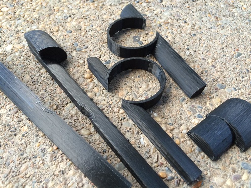
It is all held together only by the accessories mounted to it, but it seems quite solid. Originally the top and bottom parts were identical, but I had to change to an offset design to mount the light higher. The larger lobe is to accomodate the headlight's mount which is designed for an oversized bar.
Here's everything bolted up and in place, I'm very happy with the result:
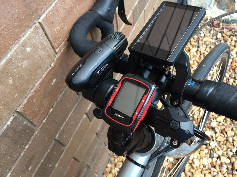
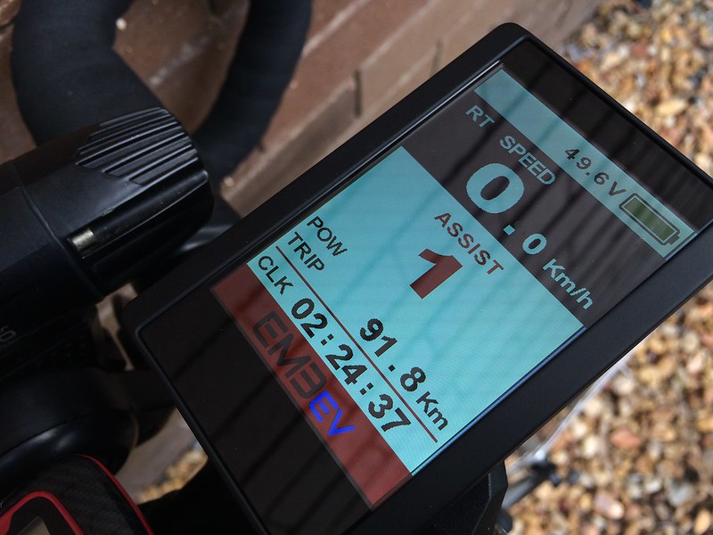
The throttle is easily within reach of my left thumb when not in the drops, and I can safely keep my right hand near the front brake at the same time. I also really like having the Bafang display quite far forward as it makes it always easy to see. The IPS display looks amazing even in direct sunlight:
I took the bike for a test ride and wasn't able to wipe the grin from my face! Talk about making cycling effortless!
Here's the bike fully completed, although disregard the low seat hight:
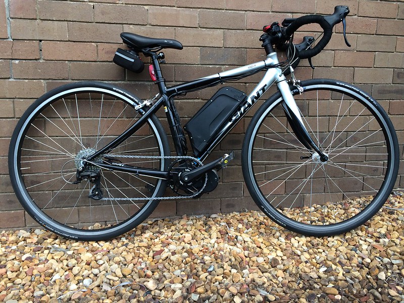
The 42/11-30 gearing seems to work quite well for my intended purpose of using this bike as a commuter.
I have a warning though; I have used the bike four times now and have done about 90km. In the last 10km I noticed a bit of a clicking noise when pedalling, it turns out the lock ring had become slightly lose. This surprised me as I used thread locker and applied the correct amount of torque to the lock ring, I assumed the ones having trouble weren't doing the install correctly. Today I re-tightened the lock ring to "epic tight" and will monitor it.
Continued at Electric bike build part 6.
After about 6 revisions I finally had a workable design for mounting my accessories. I decided to design a mount in two parts that when brought together form a ring around the stem to allow a second "row" of stuff to be mounted.
Here's the final design:
It is all held together only by the accessories mounted to it, but it seems quite solid. Originally the top and bottom parts were identical, but I had to change to an offset design to mount the light higher. The larger lobe is to accomodate the headlight's mount which is designed for an oversized bar.
Here's everything bolted up and in place, I'm very happy with the result:
The throttle is easily within reach of my left thumb when not in the drops, and I can safely keep my right hand near the front brake at the same time. I also really like having the Bafang display quite far forward as it makes it always easy to see. The IPS display looks amazing even in direct sunlight:
I took the bike for a test ride and wasn't able to wipe the grin from my face! Talk about making cycling effortless!
Here's the bike fully completed, although disregard the low seat hight:
The 42/11-30 gearing seems to work quite well for my intended purpose of using this bike as a commuter.
I have a warning though; I have used the bike four times now and have done about 90km. In the last 10km I noticed a bit of a clicking noise when pedalling, it turns out the lock ring had become slightly lose. This surprised me as I used thread locker and applied the correct amount of torque to the lock ring, I assumed the ones having trouble weren't doing the install correctly. Today I re-tightened the lock ring to "epic tight" and will monitor it.
Continued at Electric bike build part 6.
Electric bike build part 4
Continued from Electric bike build part 3.
The next stage of the build was fitting the additional sensors. The kit came with a wheel speed sensor, and as my bike has drop bars I optioned two HWBS (Hidden Wire Brake Sensor) devices.
Here's the wheel speed sensor and magnet fitted, talk about a monster magnet:
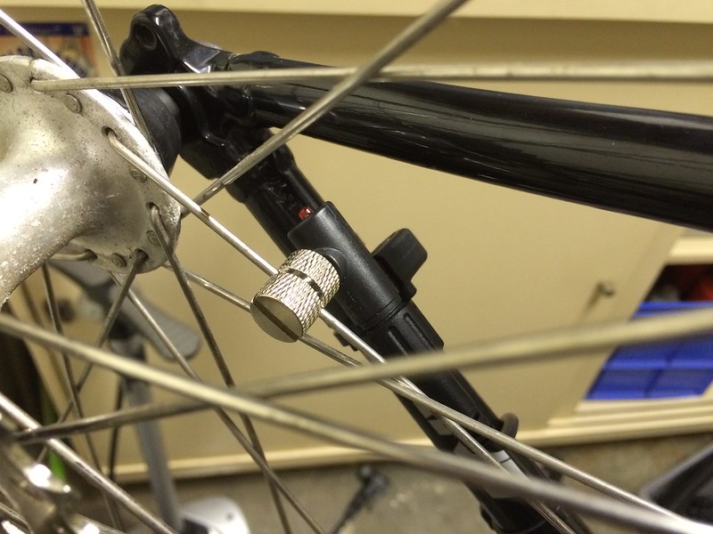
I decided to fit the brake sensors along the bars themselves by peeling back the bar tape a bit:
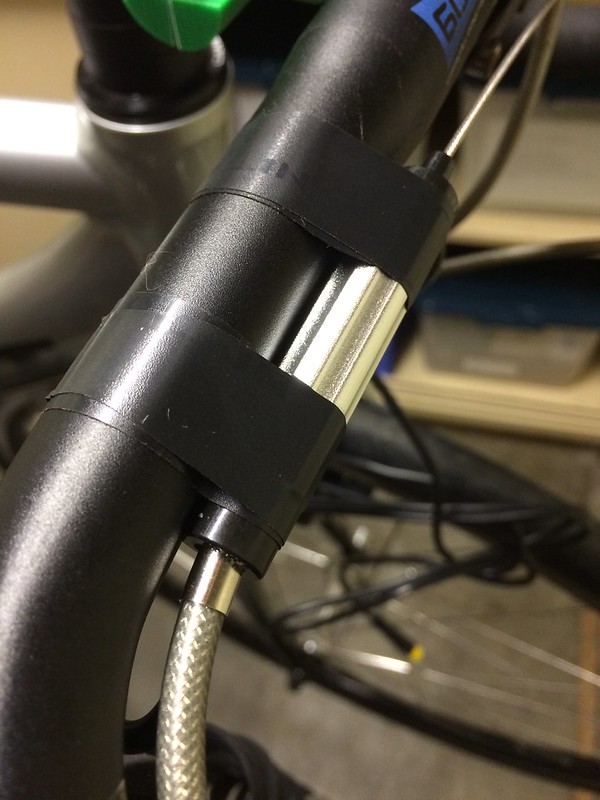
No where to be seen, and as an added bonus gives the bars quite an ergo feel:

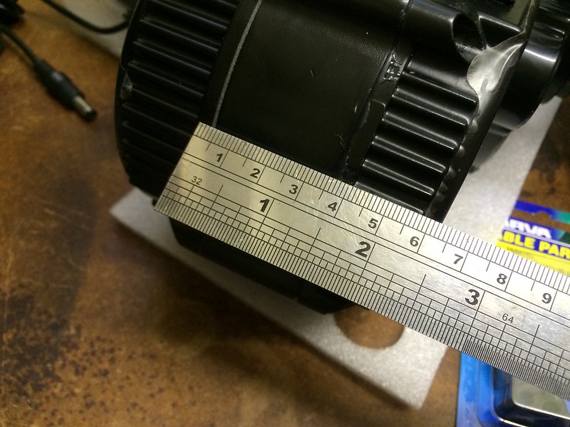
I now had to plan where to mount the screen, throttle and controls. I also had to keep room for a headlight and Garmin bike computer. The biggest problem (which I had known all along) was the internal diameter of the throttle and controls (22.2mm) being too small for my drop bars.
Having access to a 3D printer, I designed some parts to mount these accessories.
The first part I designed was a spacer for the DPC-14 display so I could orient the screen on the bracket by 180 degrees. Some Bafang documentation suggests this is possible but on my screen with a charge port, the charge port wires get in the way.
Here are some pics of the screen with the spacer fitted, and with the fasteners replaced with longer ones to retain the same thread engagement:
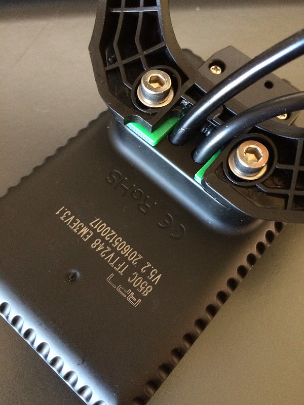


You can download the model file from Thingiverse.
Continued at Electric bike build part 5.
The next stage of the build was fitting the additional sensors. The kit came with a wheel speed sensor, and as my bike has drop bars I optioned two HWBS (Hidden Wire Brake Sensor) devices.
Here's the wheel speed sensor and magnet fitted, talk about a monster magnet:
I decided to fit the brake sensors along the bars themselves by peeling back the bar tape a bit:
No where to be seen, and as an added bonus gives the bars quite an ergo feel:
I now had to plan where to mount the screen, throttle and controls. I also had to keep room for a headlight and Garmin bike computer. The biggest problem (which I had known all along) was the internal diameter of the throttle and controls (22.2mm) being too small for my drop bars.
Having access to a 3D printer, I designed some parts to mount these accessories.
The first part I designed was a spacer for the DPC-14 display so I could orient the screen on the bracket by 180 degrees. Some Bafang documentation suggests this is possible but on my screen with a charge port, the charge port wires get in the way.
Here are some pics of the screen with the spacer fitted, and with the fasteners replaced with longer ones to retain the same thread engagement:
You can download the model file from Thingiverse.
Continued at Electric bike build part 5.
Saturday, 23 July 2016
Electric bike build part 3
Continued from Electric bike build part 2.
I now had all the parts and tools available to fit the motor to the BB shell. I had read that the high torque from the motor could dent alloy frames so I picked up some Neoprene rubber to try and reduce the chance of this happening:
Rubber applied:
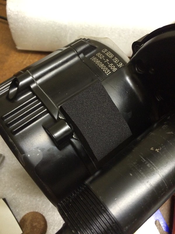
Test fit, the final fit will have the rubber fully compressed between the motor and frame:
Looks good!
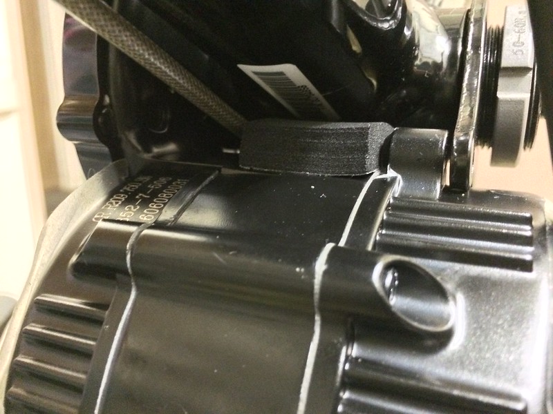
One slight issue I had was the hole on this steel bracket being drilled slightly offset, meaning the fastener wasn't able to be fitted without binding. I drilled the hole 0.5mm larger then nail polished the exposed metal:

Thanks yet again to my Aldi bike toolkit I had the right tool on hand. I was able to (blue) Loctite then tighten at the same time as holding the motor against the frame fully compressing the rubber:
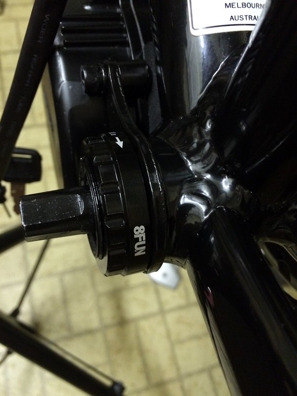
All done:
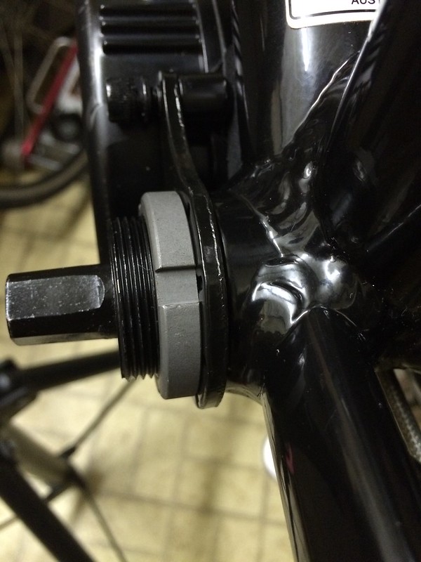
I then applied Loctite to the two additional bolts and the extra lockring (you can use a standard Shimano Hollowtech II tool) then fitted:
Here's a pic after I fitted both crankarms and chain:
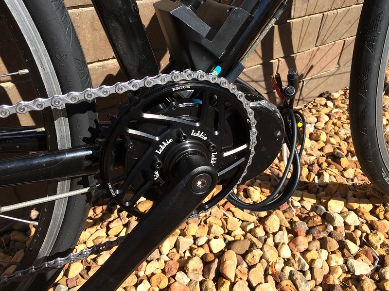
It's starting to come together!
Continued at Electric bike build part 4.
I now had all the parts and tools available to fit the motor to the BB shell. I had read that the high torque from the motor could dent alloy frames so I picked up some Neoprene rubber to try and reduce the chance of this happening:
Rubber applied:
Test fit, the final fit will have the rubber fully compressed between the motor and frame:
Looks good!
One slight issue I had was the hole on this steel bracket being drilled slightly offset, meaning the fastener wasn't able to be fitted without binding. I drilled the hole 0.5mm larger then nail polished the exposed metal:
Thanks yet again to my Aldi bike toolkit I had the right tool on hand. I was able to (blue) Loctite then tighten at the same time as holding the motor against the frame fully compressing the rubber:
All done:
I then applied Loctite to the two additional bolts and the extra lockring (you can use a standard Shimano Hollowtech II tool) then fitted:
Here's a pic after I fitted both crankarms and chain:
It's starting to come together!
Continued at Electric bike build part 4.
Monday, 18 July 2016
Electric bike build part 2
Continued from Electric bike build part 1.
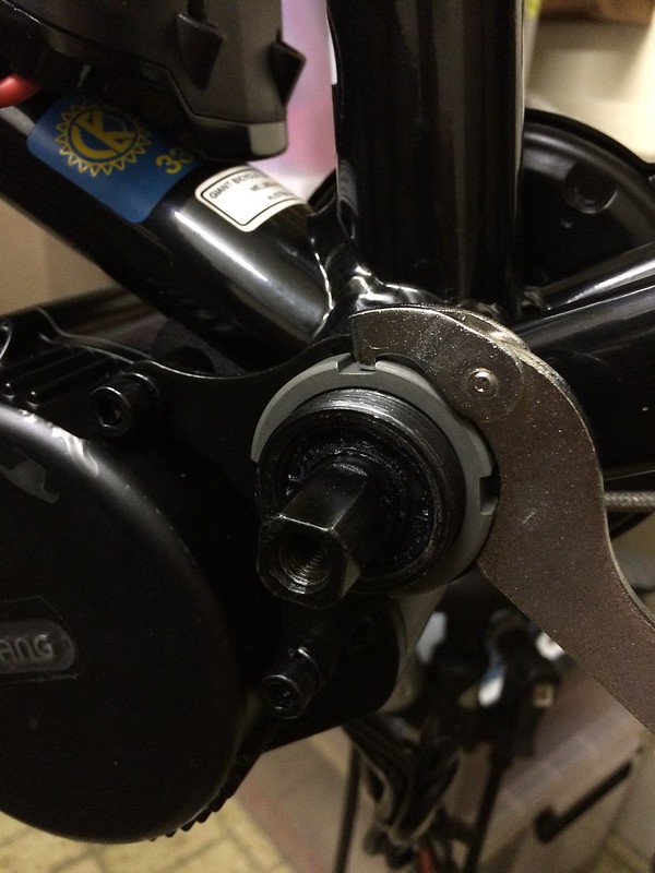
The tool now worked fine to remove the bottom bracket:
The shell looks really clean already:
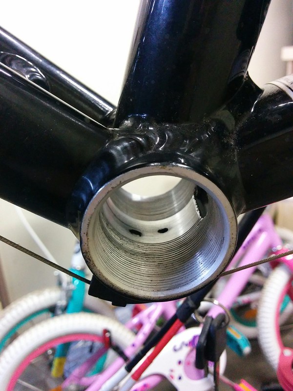
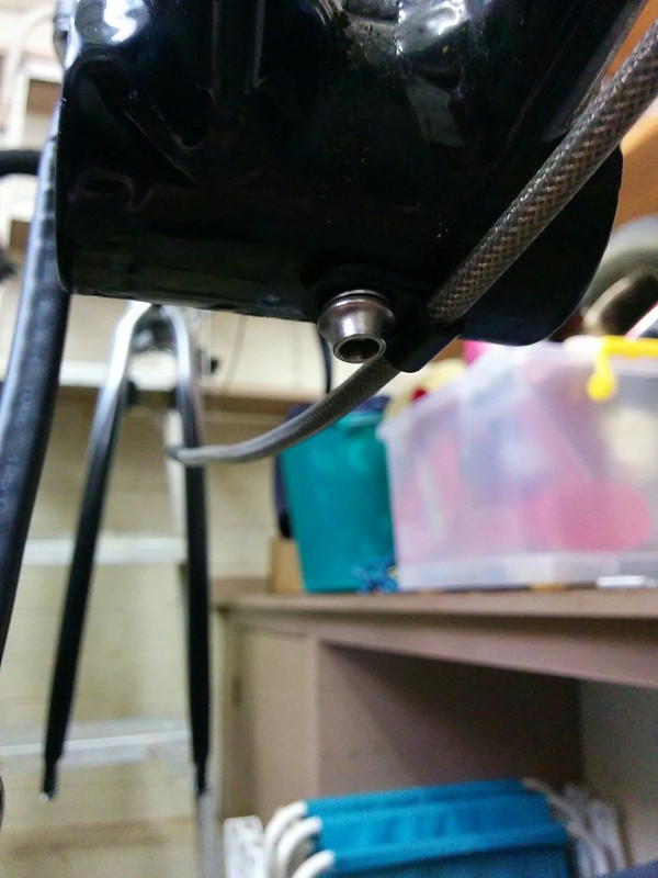
Here's the next snag, the bracket for the shifter cables gets in the way of the BBS02:
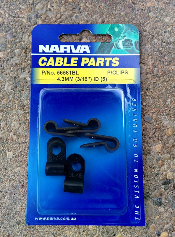
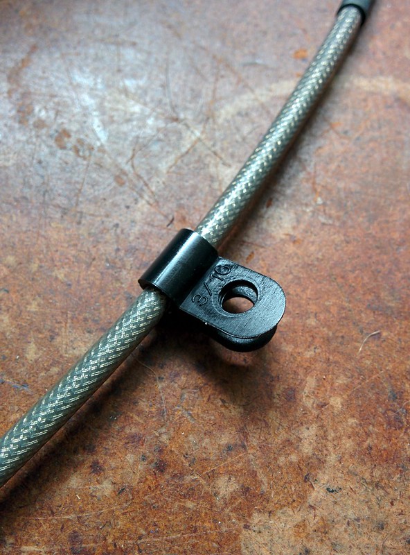
After a bit of thinking, I came up with the idea of using some cable outer tube and a cable clamp. Here are the clamps I bought:
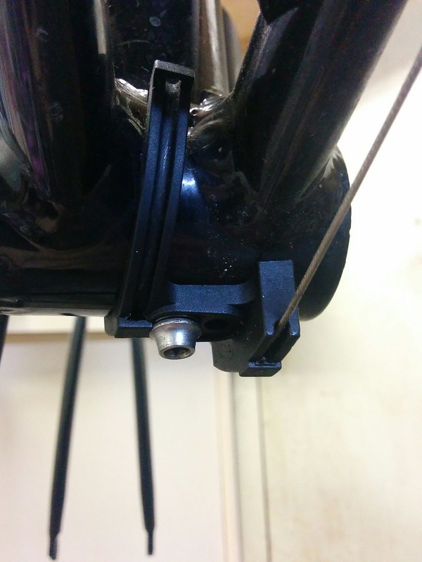
Looks promising:
Bolts up fine:
Yes! It worked:

Time will tell if this is a reliable solution, but it looks pretty good to me. I'll probably zip tie the cable outer to the frame at each side with a gentle radius.
Continued at Electric bike build part 3.
The tool now worked fine to remove the bottom bracket:
The shell looks really clean already:
Here's the next snag, the bracket for the shifter cables gets in the way of the BBS02:
After a bit of thinking, I came up with the idea of using some cable outer tube and a cable clamp. Here are the clamps I bought:
Looks promising:
Bolts up fine:
Yes! It worked:
Time will tell if this is a reliable solution, but it looks pretty good to me. I'll probably zip tie the cable outer to the frame at each side with a gentle radius.
Continued at Electric bike build part 3.
Electric bike build part 1
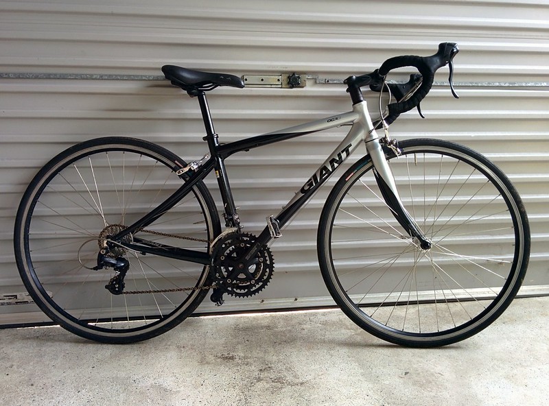
I have been collecting the bits to put together my first electric bike. It's still a work in progress so this will be my build diary. The objective is a reliable and quick road/bikeway commuter to make biking to work a more attractive option!
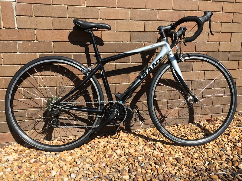
My first purchase was a used 2008 Giant OCR complete with weathered chain and perishing tyres:
At first I thought the rims were worn but it is just some surface corrosion, the bike has barely done any mileage. Importantly the frame, brakes, wheels and RD/shifters are all working well. I pretended the bike was a CX bike and took it on some trails near my house to test everything was working as intended, it all seems quite solid. The standard RD-2200 rear derailleur even worked smoothly with a 11-32 cassette!
The next step was to make a cardboard template to ensure the battery pack I intended to buy would fit, a shame both drink holders are no longer usable but looks good otherwise:
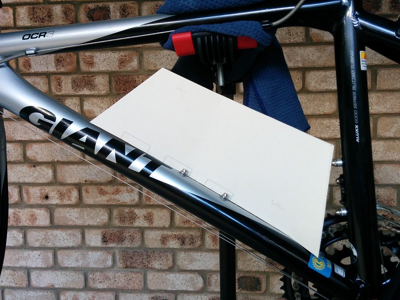
I also checked the distance between the BB shell and the outside of the frame (quite small, so no problems here), and the type of BB shell (68mm English). Everything checks out, time to pull that trigger on the order!
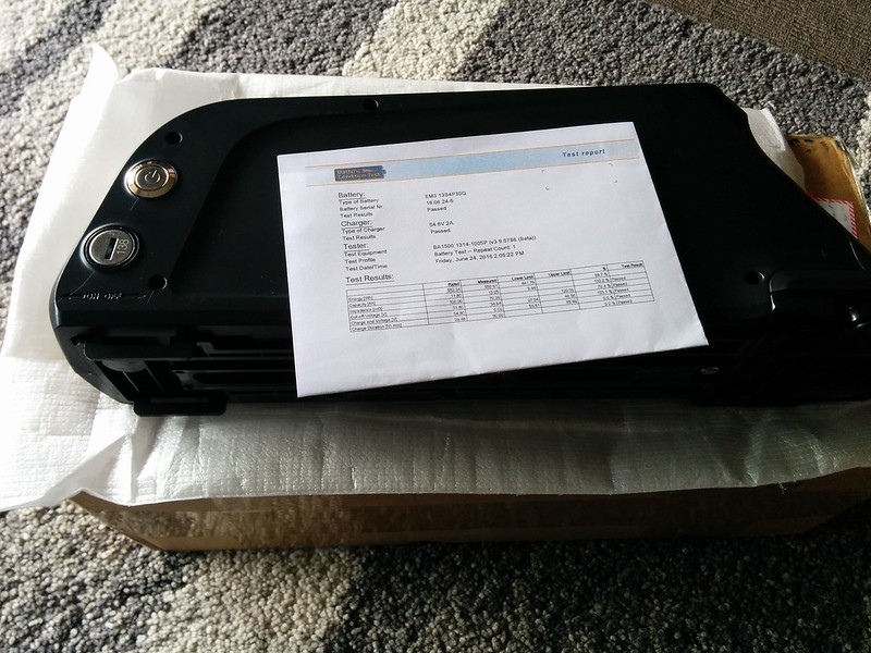
I bought the BBS02 from Paul and his team at EM3EV, my only comment is they had a shipping issue with the battery using TNT but everything was sorted out quickly by them using an alternate carrier at no cost to me. Big thumbs up for service from EM3EV, and their workmanship on the crimping/heatshrink looks great. Here are the fun bits:

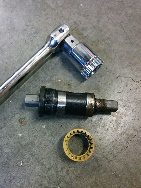
Armed with my $20 Aldi bike toolkit, I started stripping down the bike and removing the crank, the tools held up fine for this step:
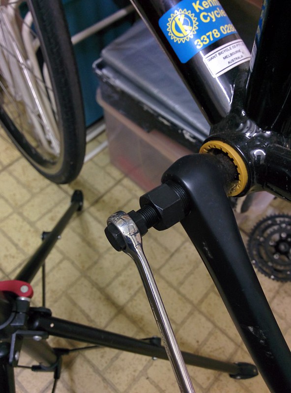
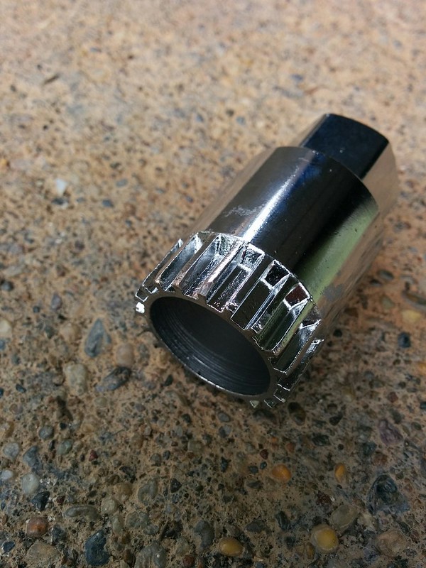
Unfortunately when I went to remove the bottom bracket cup I found the tolerances on the tool weren't good enough and some splines were too fat:

Fortunately I was able to tidy these up with an angle grinder:
I have done a test fit of the tool and it engages fine now, but I haven't gotten any further. I'll try to document the rest of the build as I go. I hope you find this build as interesting as I do!
Continued at Electric bike build part 2.
My first purchase was a used 2008 Giant OCR complete with weathered chain and perishing tyres:
At first I thought the rims were worn but it is just some surface corrosion, the bike has barely done any mileage. Importantly the frame, brakes, wheels and RD/shifters are all working well. I pretended the bike was a CX bike and took it on some trails near my house to test everything was working as intended, it all seems quite solid. The standard RD-2200 rear derailleur even worked smoothly with a 11-32 cassette!
The next step was to make a cardboard template to ensure the battery pack I intended to buy would fit, a shame both drink holders are no longer usable but looks good otherwise:
I also checked the distance between the BB shell and the outside of the frame (quite small, so no problems here), and the type of BB shell (68mm English). Everything checks out, time to pull that trigger on the order!
I bought the BBS02 from Paul and his team at EM3EV, my only comment is they had a shipping issue with the battery using TNT but everything was sorted out quickly by them using an alternate carrier at no cost to me. Big thumbs up for service from EM3EV, and their workmanship on the crimping/heatshrink looks great. Here are the fun bits:
Armed with my $20 Aldi bike toolkit, I started stripping down the bike and removing the crank, the tools held up fine for this step:
Unfortunately when I went to remove the bottom bracket cup I found the tolerances on the tool weren't good enough and some splines were too fat:
Fortunately I was able to tidy these up with an angle grinder:
I have done a test fit of the tool and it engages fine now, but I haven't gotten any further. I'll try to document the rest of the build as I go. I hope you find this build as interesting as I do!
Continued at Electric bike build part 2.
Wednesday, 17 February 2016
Aldi 3D printer
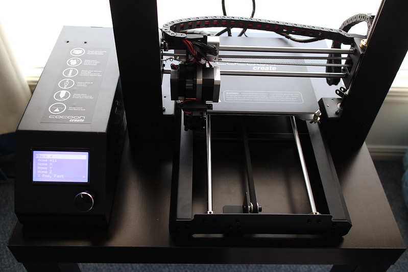
I picked up an Aldi "Cocoon Create" 3D printer this morning and spent a bit of time trying it out. It appears to be a rebranded Wanhao I3:
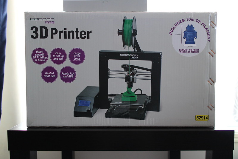
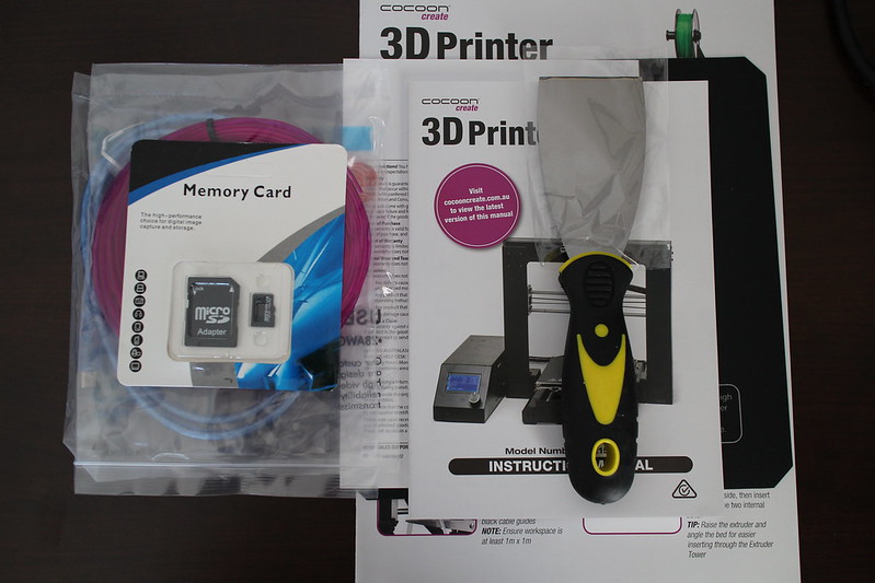
The unit was packed really well and included a few goodies including a really comprehensive printed manual:
Putting the unit together was really simple, here's the unit after following the quick start guide:
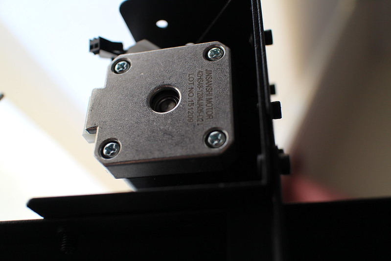
It's using Jinsanshi Motor stepper motors, they seem to be fairly quiet:
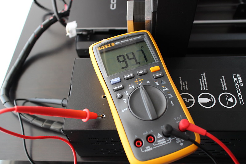
The earth pin is connected:
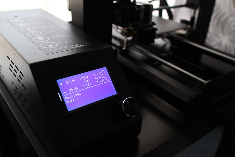
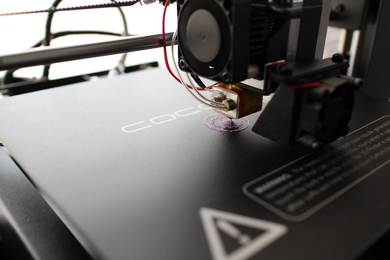
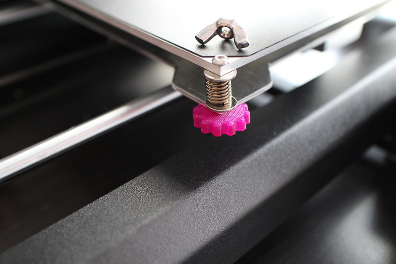
Here's a photo I took during bed levelling:

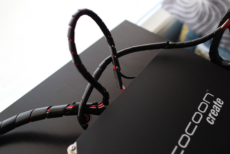
This cord was pinching a bit, so I pulled it upward to resolve the issue:
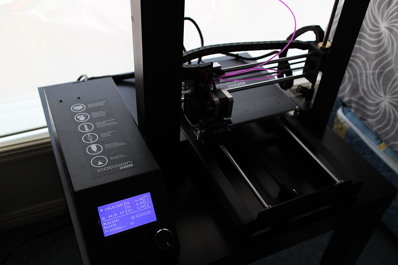
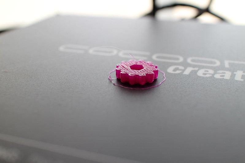
First print:
All done:
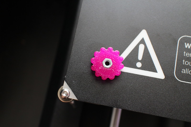
Improving the machine already:
I'm really quite impressed with this machine especially given the price point. I was up and away printing a job within 15 minutes of opening the box.
The only thing I can whine about is the power supply fan which is unnecessarily loud. You certainly wouldn't want to have the thing running all day in the same room in an office environment.
The unit was packed really well and included a few goodies including a really comprehensive printed manual:
Putting the unit together was really simple, here's the unit after following the quick start guide:
The earth pin is connected:
Here's a photo I took during bed levelling:
This cord was pinching a bit, so I pulled it upward to resolve the issue:
First print:
All done:
Improving the machine already:
I'm really quite impressed with this machine especially given the price point. I was up and away printing a job within 15 minutes of opening the box.
The only thing I can whine about is the power supply fan which is unnecessarily loud. You certainly wouldn't want to have the thing running all day in the same room in an office environment.
Saturday, 30 January 2016
First play with the BitScope Micro
I picked up a BitScope Micro to teach myself a bit about oscilloscopes. So far I've only used the first analog channel to monitor the wave generator, but it seems to do what it says on the box:
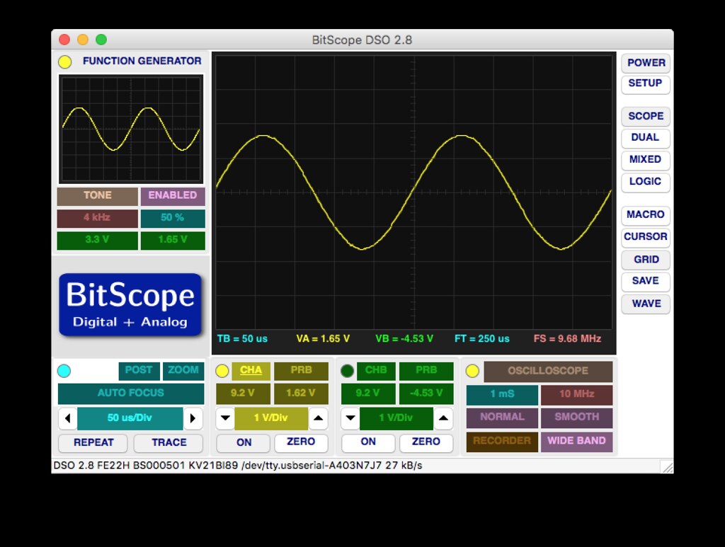
The test leads aren't the best quality, but otherwise this looks like a useful tool. You can't expect it to be in the same league as the professional gear, but for the money it's great for learning.
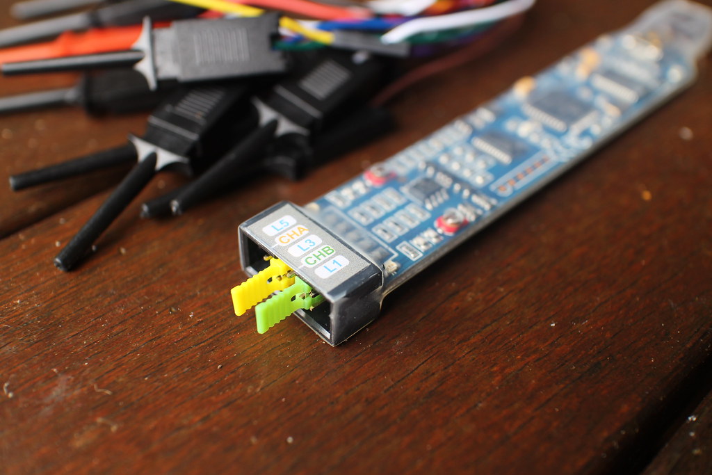
The test leads aren't the best quality, but otherwise this looks like a useful tool. You can't expect it to be in the same league as the professional gear, but for the money it's great for learning.
Saturday, 23 January 2016
Modifying the (Aldi) Lumina coffee grinder to produce a finer grind
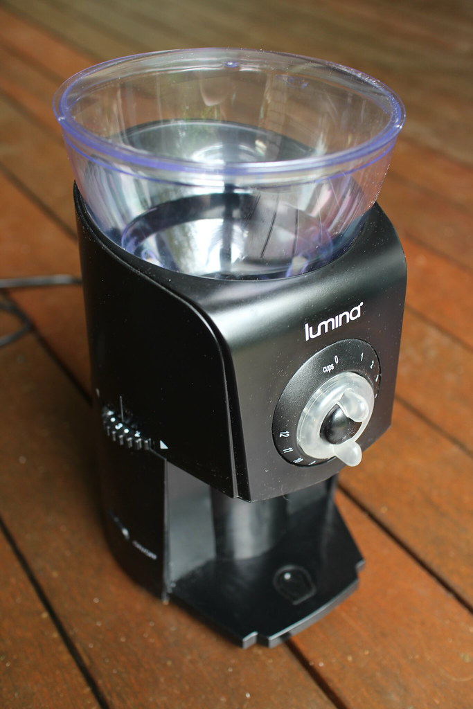
As this machine uses burrs to do the grinding I thought I'd try shimming one of the burrs to bring the two closer together, hopefully resulting in a finer grind. This actually ended up working really well, and I've been using it at least three times a week for a few months now for all my coffee grinding duties!
Here's what you will need to do the modification:
- Useless Lumina coffee grinder.
- Suitably sized Phillips head driver (you'll want to make sure it is clean).
- Three 8x1mm washers (again, make sure they are clean).
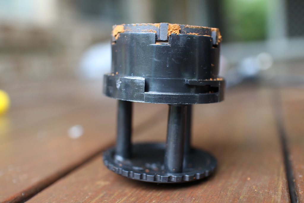
First of all you'll want to remove the top burr assembly, which you can do by turning it clockwise:
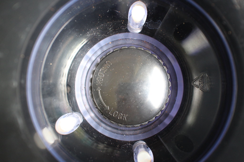
You can see the tabs that lock it into place here:
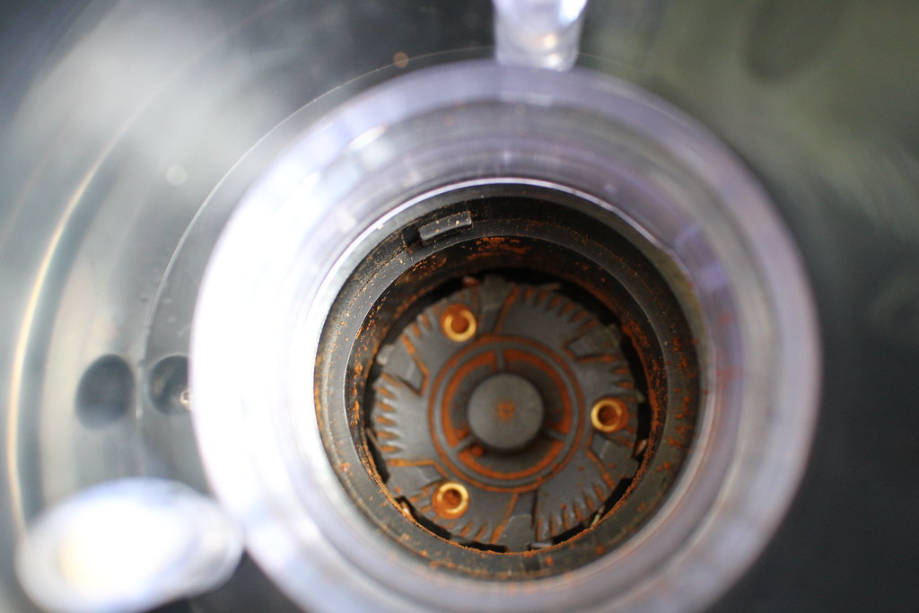
Once you've removed it, flip it upside down and you should be able to see three Phillips head screws, you'll want to remove these:
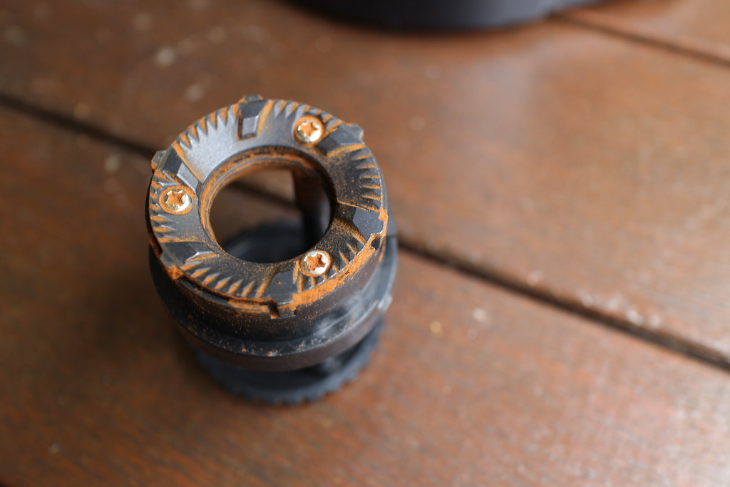
Lift the metal burr away from the rest of the plastic assembly and you will then be able to fit the three 8x1mm washers as per the picture:
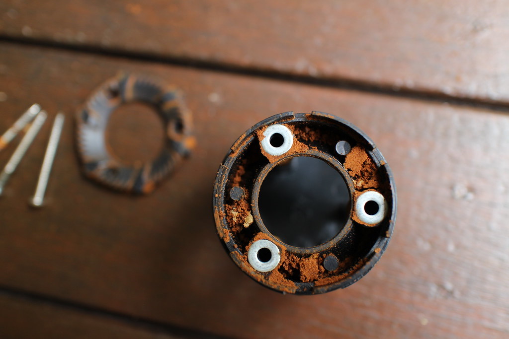
As you can see this has shimmed the burr by 1mm:
Fit the burr back onto the assembly and fasten the screws, don't go overboard with force though as they are just screwing into plastic.
Adjust the machine to the coarse setting and insert the top burr assembly, lock it into place by turning anti-clockwise.
Test out some grinding!
Subscribe to:
Posts (Atom)